Product Description
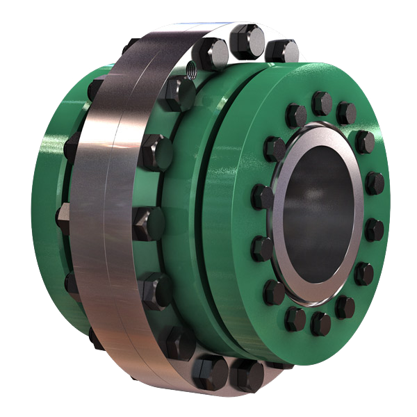
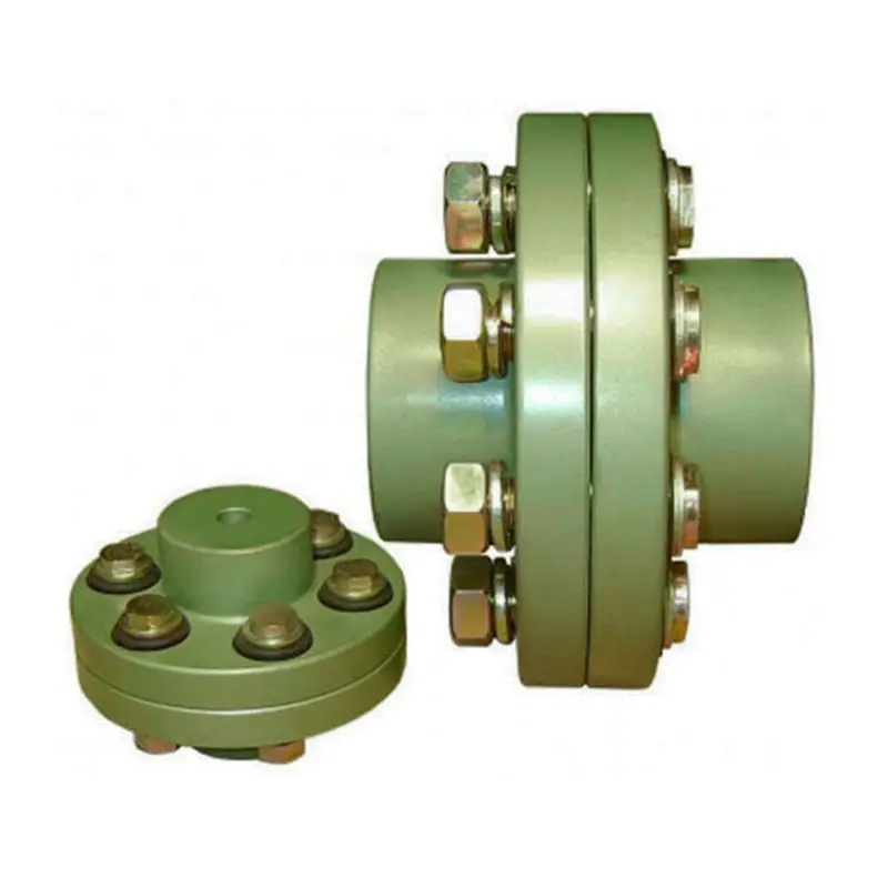
GFC-20×25 Type Aluminum Alloy Shaft Flange Coupling Flexible Shaft Coupling
Description of GFC-20×25 Type Aluminum Alloy Shaft Flange Coupling Flexible Shaft Coupling
| model parameter | common bore diameter d1,d2 | ΦD | L | LF | LP | F | M | tightening screw torque (N.M) |
| GFC-14X22 | 3,4,5,6,6.35 | 14 | 22 | 14.3 | 6.6 | 5.0 | M2.5 | 1.0 |
| GFC-20×25 | 3,4,5,6,6.35,7,8,9,9.525,10 | 20 | 25 | 16.7 | 8.6 | 5.9 | M3 | 1.5 |
| GFC-20X30 | 3,4,5,6,6.35,7,8,9,9.525,10 | 20 | 30 | 19.25 | 8.6 | 5.9 | M3 | 1.5 |
| GFC-25X30 | 4,5,6,6.35,7,8,9,9.525,10,11,12 | 25 | 30 | 20.82 | 11.6 | 8.5 | M4 | 2.5 |
| GFC-25X34 | 4,5,6,6.35,7,8,9,9.525,10,11,12 | 25 | 34 | 22.82 | 11.6 | 8.5 | M4 | 2.5 |
| GFC-30×35 | 5,6,6.35,7,8,9,10,11,12,12.7,14,15,16 | 30 | 35 | 23 | 11.5 | 10 | M4 | 2.5 |
| GFC-30X40 | 5,6,6.35,7,8,9,10,11,12,12.7,14,15,16 | 30 | 40 | 25 | 11.5 | 10 | M4 | 2.5 |
| GFC-40X50 | 6,8,9,10,11,12,12.7,14,15,16,17,18,19,20,22,24 | 40 | 50 | 32.1 | 14.5 | 14 | M5 | 7 |
| GFC-40X55 | 6,8,9,10,11,12,12.7,14,15,16,17,18,19,20,22,24 | 40 | 55 | 34.5 | 14.5 | 14 | M5 | 7 |
| GFC-40X66 | 6,8,910,11,12,12.7,14,15,16,17,18,19,20,22,24 | 40 | 66 | 40 | 14.5 | 14 | M5 | 7 |
| GFC-55X49 | 10,11,12,12.7,14,15,16,17,18,19,20,22,24,25,28,30,32 | 55 | 49 | 32 | 16.1 | 13.5 | M6 | 12 |
| GFC-55X78 | 8,10,12,12.7,14,15,16,17,18,19,20,22,24,25,28,30,32 | 55 | 78 | 46.4 | 16.1 | 19 | M6 | 12 |
| GFC-65X80 | 14,15,16,17,18,19,20,22,24,25,28,30,32,35,38,40 | 65 | 80 | 48.5 | 17.3 | 14 | M8 | 20 |
| GFC-65X90 | 14,15,16,17,18,19,20,22,24,25,28,30,32,35,38,40 | 65 | 90 | 53.5 | 17.3 | 22.5 | M8 | 20 |
| GFC-80X114 | 19,20,22,24,25,28,30,32,35,38,40,42,45 | 80 | 114 | 68 | 22.5 | 16 | M8 | 20 |
| GFC-95X126 | 19,20,22,24,25,28,30,32,35,38,40,42,45,50,55 | 95 | 126 | 74.5 | 24 | 18 | M10 | 30 |
| model parameter | Rated torque (N.M)* |
allowable eccentricity (mm)* |
allowable deflection angle (°)* |
allowable axial deviation (mm)* |
maximum speed rpm |
static torsional stiffness (N.M/rad) |
moment of inertia (Kg.M2) |
Material of shaft sleeve | Material of shrapnel | surface treatment | weight (g) |
| GFC-14X22 | 5.0 | 0.1 | 1 | ±02 | 10000 | 50 | 1.0×10⁻⁶ | High strength aluminum alloy | Polyurethane imported from Germany | Anodizing treatment | 10 |
| GFC-20X25 | 5.0 | 0.1 | 1 | ±02 | 10000 | 50 | 1.0×10⁻⁶ | 15 | |||
| GFC-20X30 | 5.0 | 0.1 | 1 | ^02 | 10000 | 53 | 1.1×10⁻⁶ | 19 | |||
| GFC-25X30 | 10 | 0.1 | 1 | 10000 | 90 | 5.2X10⁻⁶ | 33 | ||||
| GFC-25X34 | 10 | 0.1 | 1 | £)2 | 10000 | 90 | 5.2×10⁻⁶ | 42 | |||
| GFC-30X35 | 12.5 | 0.1 | 1 | ±02 | 10000 | 123 | 6.2×10⁻⁶ | 50 | |||
| GFC-30×40 | 12.5 | 0.1 | 1 | 102 | 10000 | 123 | 6.2×10⁻⁶ | 60 | |||
| GFC-40X50 | 17 | 0.1 | 1 | 8000 | 1100 | 3.8×10⁻⁵ | 115 | ||||
| GFC-40X55 | 17 | 0.1 | 1 | ±02 | 8000 | 1100 | 3.8×10⁻⁵ | 127 | |||
| GFC-40X66 | 17 | 0.1 | 1 | 7000 | 1140 | 3.9×10⁻⁵ | 154 | ||||
| GFC-55X49 | 45 | 0.1 | 1 | ±02 | 6500 | 2350 | 1.6×10⁻³ | 241 | |||
| GFC-55X78 | 45 | 0.1 | 1 | 102 | 6000 | 2500 | 1.6×10⁻³ | 341 | |||
| GFC-65X80 | 108 | 0.1 | 1 | ±02 | 5500 | 4500 | 3.8×10⁻³ | 433 | |||
| GFC-65X90 | 108 | 0.1 | 1 | ±02 | 5500 | 4800 | 3.8×10⁻³ | 583 | |||
| GFC-80X114 | 145 | 0.1 | 1 | £)2 | 4500 | 5000 | 1.8×10⁻³ | 1650 | |||
| GFC-95X126 | 250 | 0.1 | 1 | ±02 | 4000 | 5000 | 2.0×10⁻³ | 1000 |
/* March 10, 2571 17:59:20 */!function(){function s(e,r){var a,o={};try{e&&e.split(“,”).forEach(function(e,t){e&&(a=e.match(/(.*?):(.*)$/))&&1

Factors to Consider When Choosing a Flange Coupling for a Specific System
When selecting a flange coupling for a specific system, several factors need to be taken into consideration to ensure optimal performance and reliability. Here are the key factors to consider:
- 1. Load and Torque Requirements: Determine the maximum load and torque that the flange coupling will experience in the application. This includes both static and dynamic loads. Select a flange coupling that can handle these loads without exceeding its rated capacity.
- 2. Shaft Diameter: Measure the diameter of the shafts that will be connected by the flange coupling. Ensure that the coupling’s bore size matches the shaft diameter to provide a proper fit and secure connection.
- 3. Misalignment Tolerance: Consider the amount of misalignment that the system may experience during operation. Flange couplings are available in different designs, and some can accommodate higher levels of misalignment than others. Choose a coupling that can handle the expected misalignment to prevent premature wear and stress on the system.
- 4. Operating Speed: Determine the rotational speed of the connected equipment. High-speed applications may require precision balancing and careful selection of materials to prevent issues like resonance and excessive vibration.
- 5. Environmental Conditions: Consider the environmental factors the flange coupling will be exposed to, such as temperature, humidity, dust, and chemicals. Choose a material and coating that can withstand the specific environmental conditions to prevent corrosion and degradation.
- 6. Space Limitations: Evaluate the available space for installing the flange coupling. Some applications may have limited space for coupling installation, requiring compact designs or custom solutions.
- 7. Serviceability: Assess the ease of installation and maintenance of the flange coupling. A coupling that is easy to install and service can reduce downtime and maintenance costs.
- 8. Compatibility: Ensure that the flange coupling is compatible with the equipment and shafts in the system. Consider factors such as keyways, set screws, and other connection methods.
- 9. Material Selection: Choose the appropriate material for the flange coupling based on factors like load, temperature, and corrosion resistance. Common materials include steel, stainless steel, aluminum, and various alloys.
- 10. Cost: Compare the cost of different flange coupling options, considering both the initial investment and long-term maintenance expenses. Balance the cost with the desired performance and reliability.
It is essential to consult with coupling manufacturers or industry experts to ensure the flange coupling’s suitability for the specific application. Properly selecting and installing the right flange coupling can contribute to the efficiency, reliability, and longevity of the connected machinery and system.

How Does a Flange Coupling Help in Power Transmission Efficiency?
A flange coupling plays a crucial role in improving power transmission efficiency in mechanical systems. It efficiently transfers power from one shaft to another while maintaining the alignment and minimizing energy losses. Here’s how flange couplings contribute to power transmission efficiency:
1. Direct Power Transfer: Flange couplings provide a direct connection between the driving and driven shafts, ensuring a solid and reliable power transfer without the need for intermediate components. This direct coupling minimizes power losses that can occur in systems with multiple components and connections.
2. Rigid and Precise Connection: Rigid flange couplings offer a precise and firm connection between shafts, minimizing angular and parallel misalignments. By reducing misalignment, energy losses due to friction and vibrations are minimized, leading to more efficient power transmission.
3. Absence of Slippage: Flange couplings are designed to provide a secure and non-slip connection between shafts. Unlike some other coupling types that might experience slippage under heavy loads or during acceleration, flange couplings maintain constant power transmission without loss of torque.
4. High Load-Carrying Capacity: Flange couplings are capable of handling high torque and axial loads, making them suitable for heavy-duty applications. The ability to handle these loads without deformation ensures efficient power transmission even in demanding industrial settings.
5. Minimal Maintenance: Flange couplings are generally low-maintenance components. Once properly installed, they require minimal attention, reducing downtime and enhancing overall system efficiency.
6. Balancing and Vibration Damping: Some flange coupling designs, such as flexible and torsionally flexible couplings, provide additional benefits like vibration damping and torsional flexibility. These features help to absorb shocks and vibrations, ensuring a smoother power transmission and protecting connected equipment from damage.
7. Selection of Appropriate Flange Type: Choosing the right type of flange coupling for a specific application is crucial for optimal power transmission efficiency. Different flange designs offer varying levels of flexibility and alignment capabilities, allowing engineers to select the most suitable coupling based on the system requirements.
In summary, flange couplings facilitate efficient power transmission by maintaining alignment, reducing energy losses, and providing a robust and reliable connection between shafts. Properly selected and installed flange couplings help improve the overall efficiency and performance of mechanical systems.

How Does a Flange Coupling Protect Connected Equipment from Shock Loads and Vibrations?
A flange coupling plays a crucial role in protecting connected equipment from shock loads and vibrations by absorbing and dampening the impact and oscillations. The design and material properties of flange couplings contribute to their ability to mitigate shock and vibrations effectively. Below are the key factors explaining how flange couplings provide protection:
1. Flexibility: Flexible flange couplings are designed with elastomeric or metallic elements that offer flexibility between the connected shafts. When subjected to shock loads or vibrations, these elements can absorb and dissipate the energy, preventing it from transmitting to the connected equipment. The flexibility allows the coupling to accommodate misalignment and minor shocks, reducing the stress on the system.
2. Damping Properties: Elastomeric elements used in certain flange coupling designs possess inherent damping properties. These materials can absorb and dissipate vibrational energy, reducing resonance and preventing harmful vibrations from being amplified in the system.
3. Misalignment Compensation: Flange couplings with flexible elements can compensate for certain degrees of misalignment between the shafts. Misalignment can lead to additional forces and vibrations in the system, but the coupling’s ability to accommodate this misalignment reduces the impact on the connected equipment.
4. Resilience: Flange couplings made from materials like steel or other alloys have high resilience and can withstand sudden shock loads without permanent deformation. This resilience helps maintain the coupling’s integrity and allows it to continue functioning effectively after exposure to shock events.
5. Friction Damping: Some rigid flange coupling designs incorporate friction damping features. These couplings rely on friction between the mating surfaces to dampen vibrations and prevent resonant frequencies from causing issues in the system.
6. Material Selection: The choice of materials for both flexible and rigid flange couplings is critical in their ability to protect connected equipment from shock loads and vibrations. High-quality materials with appropriate mechanical properties, such as strength and elasticity, enhance the coupling’s ability to withstand shocks and vibrations.
7. Proper Installation: Correct installation and alignment of the flange coupling are essential to ensure it functions as intended. Properly installed couplings can effectively manage shocks and vibrations, while misaligned couplings may experience premature wear and transmit higher forces to the connected equipment.
8. Maintenance: Regular maintenance, including inspection, lubrication, and monitoring, ensures that the flange coupling continues to provide protection against shocks and vibrations throughout its service life.
In summary, flange couplings protect connected equipment from shock loads and vibrations by providing flexibility, damping properties, misalignment compensation, resilience, and friction damping. The selection of suitable materials, proper installation, and regular maintenance further enhance their performance in protecting industrial machinery and equipment from potential damage caused by dynamic forces.


editor by CX 2024-02-18
