
Product Description
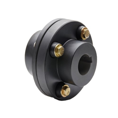
LMD Single Flange Type Plum Elastic Coupling(GB/T 5272-2002)
Product Description
♦Description
Plum elastic coupling has the characteristics of vibration reduction, buffering, small radial size, no lubrication, and easy maintenance. Suitable for starting frequency, positive and negative rotation, medium and low speed, medium and small power transmission.Not suitable for heavy loads and frequent replacement of elastic elements.
The structure of plum elastic coupling is simple. But when the elastic element is replaced, the half coupling shall be moved axially. LMS type easily replaces the elastic element without having to move the half coupling.
♦Basic Parameter and Main Dimension
| Type | Norminal torque(Tn/N·m) | Speed(Np) | Shaft hole diameter (d1,d2,dz) |
Length of the shaft hole | LO | D | D1 | Type of elastic parts | Mass | Rotary inertia | ||||||||||||||
| The hardness of elastic parts | LM | LMD, LMS | Y type | J1,Z type | L (recommend) |
LM | LMD | LMS | LMD, LMS | LM | LMD | LMS | LM | LMD | LMS | |||||||||
| a/HA | b/HD | L | ||||||||||||||||||||||
| 80+5 | 60+5 | r·min-1 | Mm | kg | kg·m2 | |||||||||||||||||||
| LM1 LMD1 LMS1 |
25 | 45 | 15300 | 8500 | 12,14 | 32 | 27 | 35 | 86 | 92 | 98 | 50 | 90 | MT1-a -b | 0.66 | 1.21 | 1.33 | 0.0002 | 0.0008 | 0.0013 | ||||
| 16,18,19 | 42 | 30 | ||||||||||||||||||||||
| 20,22,24 | 52 | 38 | ||||||||||||||||||||||
| 25 | 62 | 44 | ||||||||||||||||||||||
| LM2 LMD2 LMS2 |
50 | 100 | 1200 | 7600 | 16,18,19 | 42 | 30 | 38 | 95 | 101.5 | 108 | 60 | 100 | MT2-a -b | 0.93 | 1.65 | 1.74 | 0.0004 | 0.0014 | 0.0571 | ||||
| 20,22,24 | 52 | 38 | ||||||||||||||||||||||
| 25,28 | 62 | 44 | ||||||||||||||||||||||
| 30 | 82 | 60 | ||||||||||||||||||||||
| LM3 LMD3 LMS3 |
100 | 200 | 10900 |
6900 | 20,22,24 | 52 | 38 | 40 | 103 | 110 | 117 | 70 | 110 | MT3-a -b | 1.41 | 2.36 | 2.33 | 0.0009 | 0.0571 | 0.0034 | ||||
| 25,28 | 62 | 44 | ||||||||||||||||||||||
| 30,32 | 82 | 60 | ||||||||||||||||||||||
| LM4 LMD4 LMS4 |
140 | 280 | 9000 |
6200 | 22,24 | 52 | 38 | 45 | 114 | 122 | 130 | 85 | 125 | MT4-a -b | 2.18 | 3.56 | 3.38 | 0.002 | 0.005 | 0.0064 | ||||
| 25,28 | 62 | 44 | ||||||||||||||||||||||
| 30,32,35,38 | 82 | 60 | ||||||||||||||||||||||
| 40 | 112 | 84 | ||||||||||||||||||||||
| LM5 LMD5 LMS5 |
350 | 400 | 7300 |
5000 | 25,28 | 62 | 44 | 50 | 127 | 138.5 | 150 | 105 | 150 | MT5-a -b | 3.60 | 6.36 | 6.07 | 0.005 | 0.0135 | 0.0175 | ||||
| 30,32,35,38 | 82 | 60 | ||||||||||||||||||||||
| 40,42,45 | 112 | 84 | ||||||||||||||||||||||
| LM6 LMD6 LMS6 |
400 | 710 | 6100 |
4100 | 30,32,35,38 | 82 | 60 | 55 | 143 | 155 | 167 | 185 | 185 | MT6-a -b | 6.07 | 10.77 | 10.47 | 0.0114 | 0.0329 | 0.0444 | ||||
| 40,42,45,48 | 112 | 84 | ||||||||||||||||||||||
| LM7 LMD7 LMS7 |
630 | 1120 | 5300 | 3700 | 35*,38* | 82 | 60 | 60 | 159 | 172 | 185 | 205 | 205 | MT7-a -b | 9.09 | 15.30 | 14.22 | 0.5712 | 0.0581 | 0.571 | ||||
| 40*,42*,45,48,50,55 | 112 | 84 | ||||||||||||||||||||||
| LM8 LMD8 LMS8 |
1120 | 2240 | 4500 | 3100 | 45*,48*,50,55,56 | 112 | 84 | 70 | 181 | 195 | 209 | 170 | 240 | MT8-a -b | 13.56 | 22.72 | 21.16 | 0. 0571 | 0.1175 | 0.1493 | ||||
| 60,63,65 | 142 | 107 | ||||||||||||||||||||||
| LM9 LMD9 LMS9 |
1800 | 3550 | 3800 | 2800 | 50*,55*,56* | 112 | 84 | 80 | 208 | 224 | 240 | 200 | 270 | MT9-a -b | 21.40 | 34.44 | 30.70 | 0.1041 | 0.2333 | 0.2767 | ||||
| 60,63,65,70,71,75 | 142 | 107 | ||||||||||||||||||||||
| 80 | 172 | 132 | ||||||||||||||||||||||
| LM10 LMD10 LMS10 |
2800 | 5600 | 3300 | 2500 | 60*,63*,65*,70,71,75 | 142 | 107 | 90 | 230 | 248 | 268 | 230 | 305 | MT10-a -b | 32.03 | 51.36 | 44.55 | 0.2105 | 0.4594 | 0.5262 | ||||
| 80,85,90,95 | 172 | 132 | ||||||||||||||||||||||
| 100 | 212 | 167 | ||||||||||||||||||||||
| LM11 LMD11 LMS11 |
4500 | 9000 | 2900 | 2200 | 71*,71*,75* | 142 | 107 | 100 | 260 | 284 | 308 | 260 | 350 | MT11-a -b | 49.52 | 81.30 | 70.72 | 0.4338 | 0.9777 | 1.1362 | ||||
| 80*,85*,90,95 | 172 | 132 | ||||||||||||||||||||||
| 100,110,120 | 212 | 167 | ||||||||||||||||||||||
| LM12 LMD12 LMS12 |
6300 | 12500 | 2500 | 1900 | 80*,85*,90*95 | 172 | 132 | 115 | 297 | 321 | 345 | 300 | 400 | MT12-a -b | 73.45 | 115.53 | 99.54 | 0.8205 | 1.751 | 1.9998 | ||||
| 100,110,120,125 | 212 | 167 | ||||||||||||||||||||||
| 130,140,150 | 252 | 202 | ||||||||||||||||||||||
| LM13 LMD13 LMS13 |
11200 | 2000 | 2100 | 1600 | 90*,95* | 172 | 132 | 125 | 323 | 348 | 373 | 360 | 460 | MT13-a -b | 103.86 | 161.79 | 137.53 | 1.6718 | 3.667 | 3.6719 | ||||
| 100*,110*,120*,125* | 212 | 167 | ||||||||||||||||||||||
| 130,140,150 | 252 | 202 | ||||||||||||||||||||||
| LM14 LMD14 LMS14 |
12500 | 25000 | 1900 | 1500 | 100*,110*,120*,125* | 212 | 167 | 135 | 333 | 358 | 383 | 400 | 500 | MT14-a -b | 127.59 | 196.32 | 165.25 | 2.499 | 4.8669 | 5.1581 | ||||
| 130*,140*,150 | 252 | 202 | ||||||||||||||||||||||
| 160 | 302 | 242 | ||||||||||||||||||||||
NOTE:
1. Mass and rotary inertia are the approximation calculated according to the recommended minimum axial hole.
2. Diameter of shaft hole with * can be used for Z – type shaft hole.
3. a.b is the code for 2 different materials and the hardness of elastic parts.
Other products
| Transmission Machinery Parts Name |
Model |
| Universal Coupling | WS,WSD,WSP |
| Cardan Shaft | SWC,SWP,SWZ |
| Tooth Coupling | CL,CLZ,GCLD,GIICL, GICL,NGCL,GGCL,GCLK |
| Disc Coupling | JMI,JMIJ,JMII,JMIIJ |
| High Flexible Coupling | LM |
| Chain Coupling | GL |
| Jaw Coupling | LT |
| Grid Coupling | JS |
Company Profile
HangZhou CHINAMFG Machinery Manufacturing Co., Ltd. is a high-tech enterprise specializing in the design and manufacture of various types of coupling. There are 26 employees in our company, including 2 senior engineers and no fewer than 10 mechanical design and manufacture, heat treatment, welding, and other professionals.
Advanced and reasonable process, complete detection means. Our company actively introduces foreign advanced technology and equipment, on the basis of the condition, we make full use of the advantage and do more research and innovation. Strict to high quality and operate strictly in accordance with the ISO9000 quality certification system standard mode.
Our company supplies different kinds of products. High quality and reasonable price. We stick to the principle of “quality first, service first, continuous improvement and innovation to meet the customers” for the management and “zero defect, zero complaints” as the quality objective.
Our service
1. Design Services
Our design team has experience in Cardan shafts relating to product design and development. If you have any needs for your new product or wish to make further improvements, we are here to offer our support.
2. Product Services
Raw materials → Cutting → Forging →Rough machining →Shot blasting →Heat treatment →Testing →Fashioning →Cleaning→ Assembly→ Packing→ Shipping
3. Samples Procedure
We could develop the sample according to your requirement and amend the sample constantly to meet your need.
4. Research & Development
We usually research the new needs of the market and develop the new model when there is new cars in the market.
5. Quality Control
Every step should be a special test by Professional Staff according to the standard of ISO9001 and TS16949.
FAQ
Q 1: Are you a trading company or a manufacturer?
A: We are a professional manufacturer specializing in manufacturing various series of couplings.
Q 2: Can you do OEM?
Yes, we can. We can do OEM & ODM for all the customers with customized artworks in PDF or AI format.
Q 3: How long is your delivery time?
Generally, it is 20-30 days if the goods are not in stock. It is according to quantity.
Q 4: Do you provide samples? Is it free or extra?
Yes, we could offer the sample but not for free. Actually, we have a very good price principle, when you make the bulk order the cost of the sample will be deducted.
Q 5: How long is your warranty?
A: Our Warranty is 12 months under normal circumstances.
Q 6: What is the MOQ?
A: Usually our MOQ is 1 pcs.
Q 7: Do you have inspection procedures for coupling?
A: 100% self-inspection before packing.
Q 8: Can I have a visit to your factory before the order?
A: Sure, welcome to visit our factory.
Q 9: What’s your payment?
A: T/T.
♦Contact Us
Web: huadingcoupling
Add: No.11 HangZhou Road,Chengnan park,HangZhou City,ZheJiang Province,China
/* January 22, 2571 19:08:37 */!function(){function s(e,r){var a,o={};try{e&&e.split(“,”).forEach(function(e,t){e&&(a=e.match(/(.*?):(.*)$/))&&1
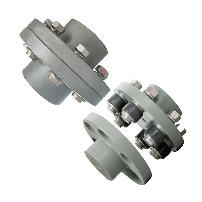
Flange Couplings for Motor-to-Shaft and Shaft-to-Shaft Connections
Flange couplings are versatile components that can be used for both motor-to-shaft and shaft-to-shaft connections in a wide range of mechanical systems. Their design and features make them suitable for various applications:
1. Motor-to-Shaft Connections: Flange couplings are commonly used to connect electric motors to driven equipment, such as pumps, fans, compressors, and conveyors. In motor-to-shaft connections, the flange coupling is mounted on the motor shaft and connected to the input shaft of the driven equipment. This configuration ensures efficient power transmission from the motor to the driven component.
2. Shaft-to-Shaft Connections: Flange couplings are also employed for shaft-to-shaft connections, where two shafts need to be linked together. This could involve connecting two separate pieces of machinery or extending the length of an existing shaft. Flange couplings allow for the secure and precise alignment of the two shafts, ensuring smooth rotation and power transmission between them.
Flange couplings are available in various designs, such as rigid flange couplings, flexible flange couplings, and floating shaft couplings. Rigid flange couplings offer a more rigid connection, ideal for applications where shaft misalignment is minimal. Flexible flange couplings, on the other hand, can accommodate some degree of misalignment and provide vibration dampening, making them suitable for systems with dynamic conditions or slight misalignments.
When selecting a flange coupling for a specific connection, factors such as the required torque capacity, shaft sizes, misalignment tolerance, and operating conditions need to be considered. Proper installation and alignment are crucial to ensure the optimal performance and longevity of the flange coupling in both motor-to-shaft and shaft-to-shaft connections.
In summary, flange couplings are versatile components that can be effectively used for both motor-to-shaft and shaft-to-shaft connections. Their ability to provide secure and efficient power transmission makes them a valuable choice in various industries and mechanical systems.
Can Flange Couplings Be Used in Applications with High Shock and Impact Loads?
Yes, flange couplings are designed to handle high shock and impact loads in various industrial applications. Their robust construction and rigid design make them suitable for use in systems where sudden shocks and impacts are common.
The ability of flange couplings to withstand shock and impact loads is influenced by several factors:
1. Material Selection: Flange couplings are often made from high-strength materials, such as alloy steels or stainless steels, which provide excellent toughness and resistance to impact loads.
2. Robust Design: The design of flange couplings typically includes features like sturdy flanges and high-strength bolts that enhance their ability to withstand shocks and impacts.
3. Tolerance for Misalignment: Some flange couplings, such as flexible flange couplings, have the ability to accommodate slight misalignments between shafts. This flexibility helps absorb shocks and vibrations, reducing the impact on connected equipment.
4. Proper Installation: Proper installation and alignment are crucial for ensuring that flange couplings can handle shock and impact loads effectively. Precision alignment and the correct torque on the bolts prevent premature failures due to misalignment.
5. Application Considerations: When selecting a flange coupling for an application with high shock and impact loads, factors such as torque requirements, rotational speed, and the magnitude of the shock should be taken into account to choose the most suitable coupling type and size.
Overall, flange couplings are a reliable choice for systems where shock and impact loads are present. However, it is essential to consult with coupling manufacturers or engineering experts to ensure the proper selection and installation of the coupling for specific high-impact applications.

Advantages of Flange Couplings in Mechanical Systems
Flange couplings offer several advantages in mechanical systems, making them a popular choice for connecting shafts in various applications:
- High Torque Transmission: Flange couplings provide a rigid and secure connection between shafts, allowing for efficient transmission of high torque without slippage or power loss.
- Precise Alignment: Proper alignment of flange couplings ensures that the connected shafts are in perfect axial alignment, reducing the risk of excessive bearing loads and increasing the longevity of the machinery.
- Zero Backlash: Flange couplings have no play or free movement between the shafts, resulting in immediate torque transmission and precise motion control, especially in applications requiring precise positioning.
- Robust and Durable: Flange couplings are typically made from high-quality materials such as steel, cast iron, or aluminum, providing excellent durability and resistance to wear and corrosion.
- Wide Range of Sizes and Torque Capacities: Flange couplings are available in various sizes and configurations, allowing them to be used in a wide range of applications with different torque requirements.
- Simple Installation: Installing flange couplings is relatively straightforward, requiring alignment and fastening of the flanges with bolts and nuts.
- Wide Application Range: Flange couplings are used in various industries, including heavy machinery, pumps, compressors, marine propulsion, and power generation equipment.
- Suitable for High-Speed Applications: Flange couplings can handle high rotational speeds, making them suitable for applications requiring high-speed power transmission.
- Minimal Maintenance: Once properly installed, flange couplings require minimal maintenance, reducing downtime and operational costs.
Despite their advantages, flange couplings also have some limitations. They lack the ability to compensate for misalignment like flexible couplings, which can lead to increased stress on bearings and other components if not correctly aligned. Additionally, the rigid nature of flange couplings means they may not be suitable for applications where shaft misalignment is common or where shock and vibration absorption is required.
Overall, flange couplings are a reliable and robust choice for mechanical systems, particularly in applications demanding high torque transmission and precise shaft alignment. Proper installation and maintenance are crucial to ensure optimal performance and longevity of both the coupling and the connected machinery.


editor by CX 2024-04-17